I've designed this course as a beginner intro into programming for robotics. It's intended to let you learn a little or a lot depending on your goals. Each step builds knowledge on the previous steps, however feel free to use it however it works best for you!
This intro course is presented in levels that allow you to build a contraption that measures moisture in soil.
However the same principles apply so if you learn how to get readings from an analog moisture sensor you'll also know it's the same process to use most other analog sensors
Level 1 completing level 1 will provide you the knowledge to use any number of analog sensors (light, sound, distance, smoke, alchohol, etc.).
Level 2 you introduces you to digital output (LEDs), again the use case here is LED lights, but once you acquire the knowledge to use a DIO (Digital Input/Output) pin it is the same to power an led as it is to turn on a relay that controls a lamp, lock, piston, pneumatics, motors etc.
Level 3 We use PWM to set a precise position of a servo motor and use that to perform precisly controlled actions based on the external stimulus. In the context of this project: if the soil is too dry, it can add just the right amount of water. But precision positions is used throughout Robotics and the same basic principals will apply.
Level 1 - a sensor (analog)
Using a sensor to receive analog input with an Arduino Uno
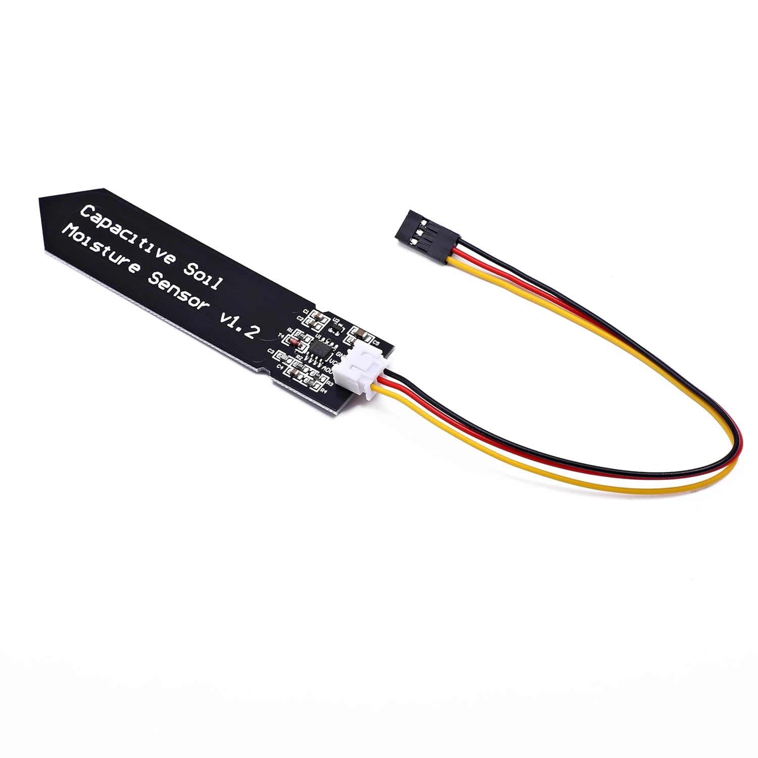
Fig.1 - Capacitive Moisture Sensor.
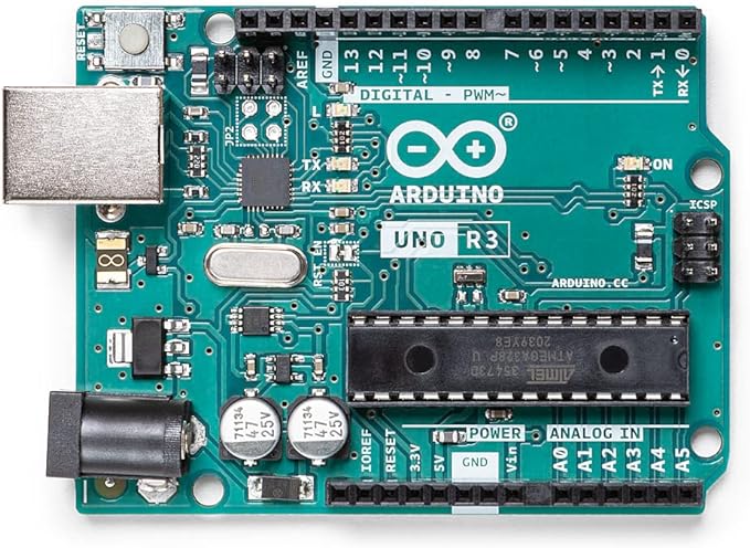
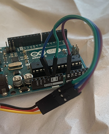
Fig.2 - Arduino Uno.
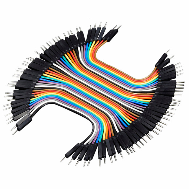
Fig.3 - Jumper Wires.
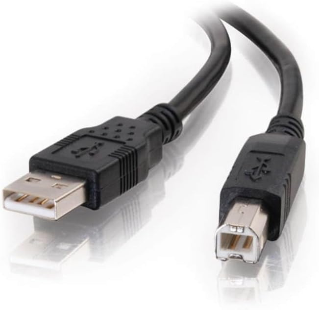
Fig.4 - USB A Cable.
Connect the Moisture Sensor to the Arduino Uno:
The moisture sensor comes with a 3 wire connector
Attach the white end of the 3 wire connector to the moisture sensor so it appears like figure 1.
Attach 3 jumper wires, 1 to the each of the 3 positions of the black end of the 3 wire connector
Attach the jumper wire that is connected to the yellow wire from the moisture sensor to the A0 pin on the Arduino Uno (The Sensor wire)
Attach the jumper wire that is connected to the red wire from the moisture sensor to the 5V pin on the Arduino Uno (The Power wire)
Attach the jumper wire that is connected to the black wire from the moisture sensor to the Gnd pin on the Arduino Uno (The Ground wire)
After step 1: Your Arduino to Moisture sensor connections should look like this:
Write and upload the code to the Arduino Uno
Attach a USB-A wire from your computer to the Arduino Uno
Open the Arduino IDE
Create a new file and paste in the code shown in blue below, each line of the code is expalined in the code explenation below
void setup() and void loop() are built into every Arduino program. void setup() runs whatever code is found within its brackets {} ONE TIME and is used to set any conditions that only need to be set once at the beginning of the code execution. void loop() runs whatever code is found within its brackets {} repeatedly forever - as long as it is not interupted or disconnected from its power source. (depending on the time it takes to run the code (an empty void loop() can run up to 4,000,000 times per second!))
Inside the void setup() brackets, you'll see only one line: Serial.begin(9600);. This line is a built in feature of Arduino that sets up Serial communication between the Arduino and your computer over the USB cable (USB stands for Universal Serial Bus). You don't need to know the inner workings of it to be able to use it, but the web is full of further information if you want to explore how Serial Communication works!
Inside the void loop() brackets, you'll see two lines: Serial.println(analogRead(A0)); and delay(1000);
The first line performs multiple actions Serial.println() will print to your "Serial Monitor" (your computer screen) whatever is inside the parenthesis, inside the parenthesis we see analogRead(A0), analogRead() is a built in arduino function that gets the reading from the pin specified inside its paranthises. In this case the A0 pin is the pin we connected between the Arduino and the Moisture sensor in our very first step!
The second line delay() simply pauses or "delays" for the number of milliseconds inside the parenthesis. 1000 milliseconds is equal to 1 second.
Save the file (using any name that you want).
In the Arduino IDE: under the tools menu, ensure that the board is set to "Arduino Uno", and the port selected shows the Arduino Uno we connected via the USB cable
Upload the code to the Arduino by clicking the "Upload" button (circle icon with an arrow pointing to the right).
Open the Serial Monitor (looks like an spy glass on the top right of the Arduino IDE) and you'll see the sensor readings!
Lets make sense of the readings and convert them to percentages
The Analog reading we see printing out on the Serial Monitor should be showing us readings similar in results to ~580 when dry to ~290 when wet (each individual sensor will be different and provide slightly different values)
It's measuring the resistance to electrons flowing across the sensor (water provides less resistance) so more moisture means less resistance, you can even wrap your fingers around the sensor and notice the moisture in your body allows the electrons to flow with less resistance
Let's convert this to a percentage - a value that makes more sense to people:
Back in the Arduino IDE, in the code we added: Just before the Serial.println, add the following line:
and then change the Serial.println to output the variable called percentage that we created with the previous line:
Serial.println(percentage);
Code Explanation
The left side of the equal sign float percentage creates a variable named "percentage" that is of type float
More Explanation
In C++ or Arduino, there are various data types like string, int, char, bool, float, and double. Each of these data types have specific values that can be stored in them.
char A char variable stores single characters, such as 'a' or 'B'.
string A string variable contains a collection of characters
int An integer variable - holds whole numbers (no decimals)
float or a double When we want to store numbers with decimals, we can either use the float or double The byte size for float is 4 while the byte size for double is 8 a float can hold up to 7 decimal digits accurately while a double can hold up to 15
bool A boolean variable holds either a True or False and must be one of those two states.
The right side of the equal sign map(analogRead(A0), 290, 580, 100, 0); uses map() to associate our highest moisture reading (290) and our lowest moisture reading (580) to their respective readings as a percentage 100 (as our highest reading) - 0 (as our lowest reading). The result of the map() is set as the value of the variable named percentage.
The Serial.println(percentage); Will print out our human readable percentage to the serial monitor
Upload and view your updated code which should now be showing percentages: 0 for dry, and 100 for wet (Some adjustments may be necessary to your high and low value readings in map() due to calibration differences of the sensors and external factors like the current humidity). See if you can "calibrate the sensor" and get the output to match 0 when dry, and 100 when dipped in water.
That's It! Congratulations, If you followed along you have built and coded an Arduino project that can measure moisture in soil. It was really quite easy, lets keep going and add some LEDs so we have output without needing it connected to a computer!
Now that we are getting readings from our moisture sensor to our computer, lets replace the output going to the computer with led lights that will allow us to know the status of our moisture sensor without being connected to a computer.
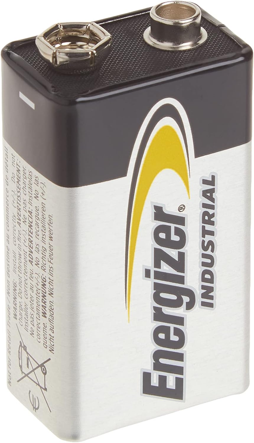
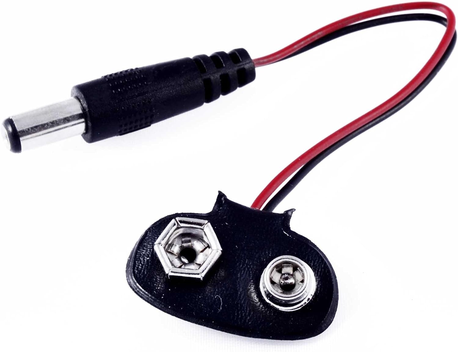
Fig.5 - 9Volt Battery.
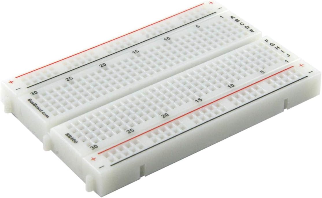
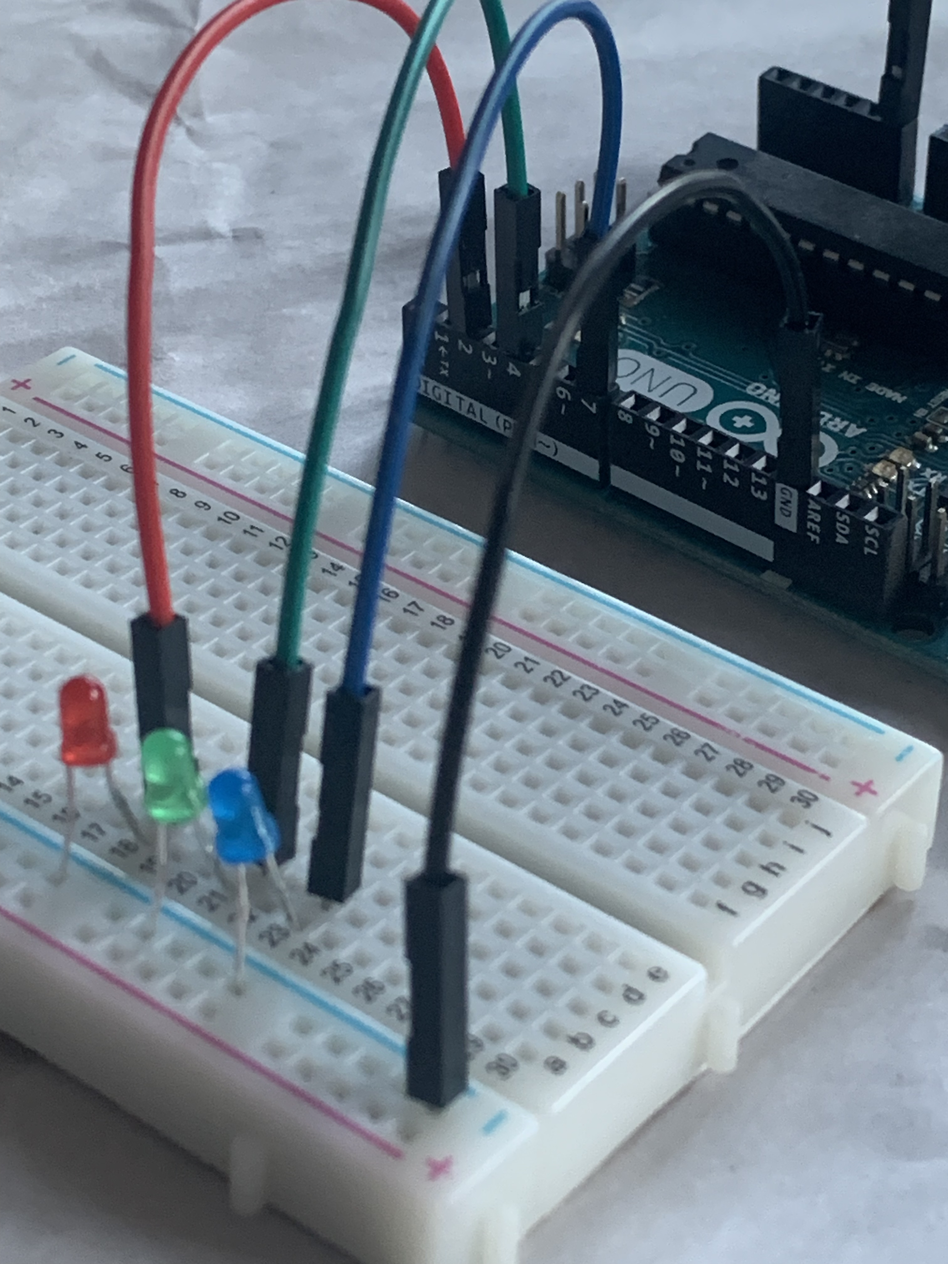
Fig.6 - BreadBoard.
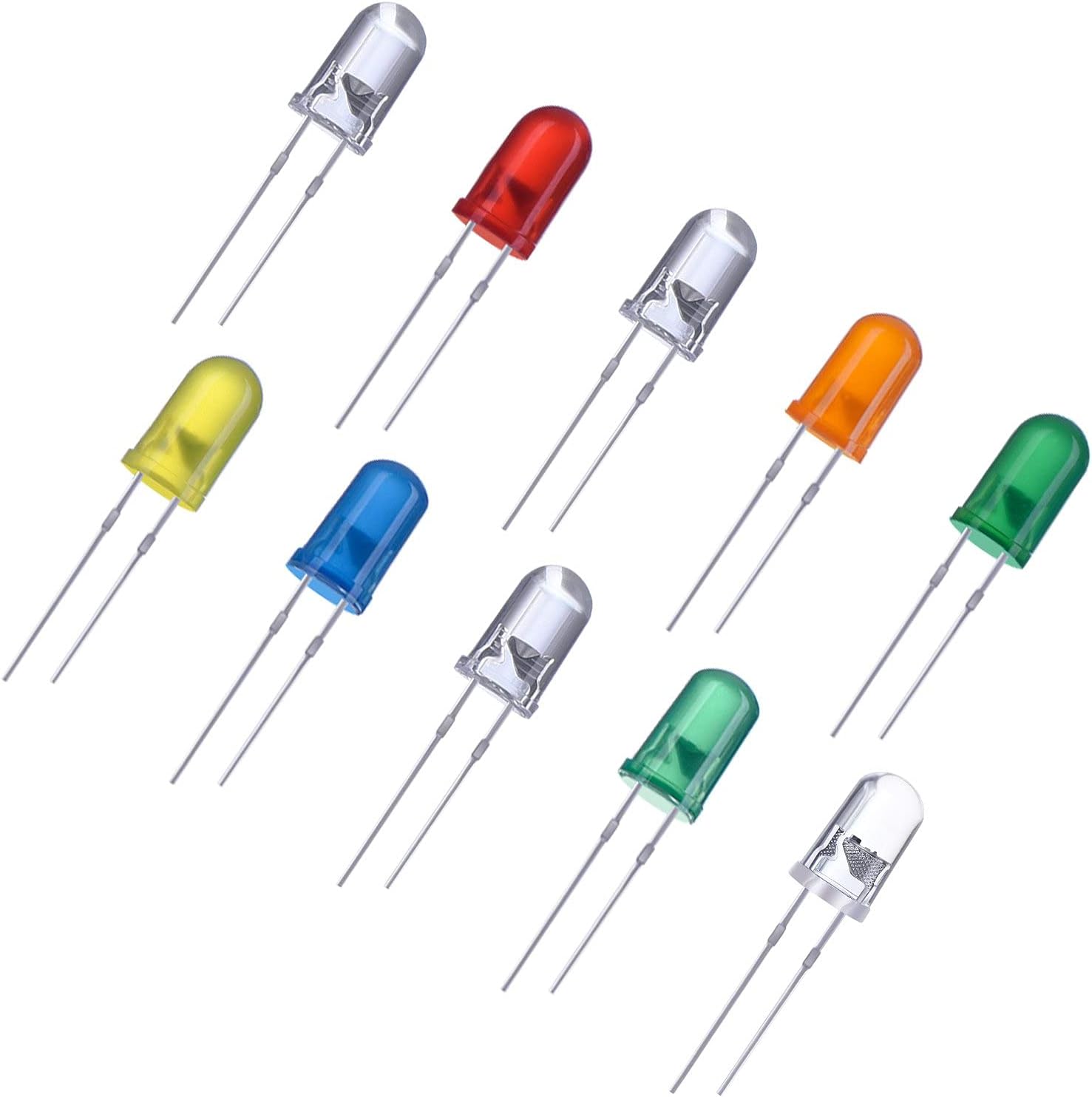
Fig.7 - LEDs.
Fig.8 - 9V to Barrel Jack.
Using a breadboard is not absolutely necessary, but it makes prototyping and experimenting a lot easier.
Note: The short leg of an led is the ground (GND) side and the long leg is positive.
Place one end of a jumper wire into the GND row of the breadboard and the other end to a Gnd pin on the Arduino making the entire row of holes GND
Place the short leg of a red led into the GND row of the breadboard and the long leg into one of the rows of holes
Place the short leg of a blue led into the GND row of the breadboard and the long leg into one of the rows of holes
Place the short leg of a green led into the GND row of the breadboard and the long leg into one of the rows of holes
You breadboard connections should look like this:
Update our code to use the LED's for visual output instead of the computer screen.
Inside the brackets of the void setup(), replace Serial.begin(9600); with:
We can remove Serial.begin(9600); because it is no longer needed, if you recall from level 1 this line sets up Serial communication between the Arduino and the Computer. In Level 2, we are not going to have output to the computer monitor, so this is no longer needed.
pinMode() is a built in Arduino function that sets up the specified pin to either be an ouput pin, or an input pin As an "INPUT" it could be used to Read the state of a DIGITAL INPUT sensor such as a button or a beam break sensor. We are using pins 2, 4 and 7 as DIGTIAL OUTPUT that will turn on or off the voltage going to the pins which will in turn turn on or off the LEDs attached to those pins.
We add: pinMode(2, OUTPUT); to setup DIO pin 2 as a DIGITAL OUTPUT
We add: pinMode(4, OUTPUT); to setup DIO pin 4 as a DIGITAL OUTPUT
We add: pinMode(7, OUTPUT); to setup DIO pin 7 as a DIGITAL OUTPUT
Inside the brackets of the void loop(), replace Serial.println(percentage); with:
This is the first time we've introduced an "if" statement, it does the same thing in computer programming as it does when we're talking to another person... if the condition inside the parenthesis evaluate to true if ( true ), Then the code inside it's brackets is executed { this code is executed }, But if the condition evaluates to false if ( false ), Then the code inside it's brackets is not executed { ..this code is not executed.. }
When an if() statement is followed by an else statement, the code in the else statement runs when the proceeding if statement evaluates to false.
The way we structured the code above, Exactly One of the scenarios for the if, else if, else block will always run (no more and no less than one of the cases will always evaluate to true OR it will execute the code in the final else block)
Disconnect the USBa cable from the Arduino (it's no longer needed).
Connect one end of your barrel jack to the 9V battery and the other end to the barrel jack on the Arduino
Your moisture sensor is now running without being connected to your computer and should be providing output that tells you the moisture readings by seeing the LEDs light up!
That's It! Congratulations, If you followed along you have built and coded an Arduino project that can measure moisture in soil and light up LED's to give us humans a visial indicator of the moisture sensor readings!.
That's not so hard, now lets turn it up a notch with Level 3 and instead of just seeing LEDs light up, lets have our moisture sensing robot automatically take action!
Note: We used an Analog sensor on an Analog pin (A0) in Level 1 (that returns a value between 0-1023). A DIO pin can be used for a Digtal Sensor - any sensor that has exactly 2 states: ON/OFF, or HIGH/LOW, or OPEN/CLOSED or 5v/0v (boolean values) by setting the pinMode() as INPUT pinMode(7, INPUT); and reading it's state with digitalRead(..pinNumber..), for example: digitalRead(7);
After completing level 2, you should now have a contraption that reads a moisture sensor and has visual output with LEDs. We are going to change that up and instead of lighting LEDs to tell us the status of the moisture sensor we are going to set a motor to a precise position.
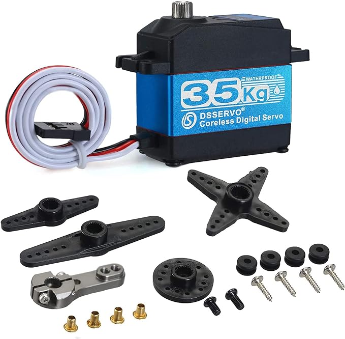
Fig.10 - Servo Motor.
Remove the jumper wires going from the breadboard to the Arduio (pins 2, 4, and 7, and Gnd) so the breadboard is no longer attached.
Using a jumper wire, connect the red wire of the servo to the Vin pin on the arduino
Using a jumper wire, connect the black wire of the servo to the GND pin on the arduino
Using a jumper wire, connect the white wire pin 3 on the arduino or any PWM pin if you adjust the code to match
Now lets re-write our Aruino code for this setup
Remove the now unecessary code from the setup() and loop() that was used to control the LEDs in the Arduino IDE After this the setup() will be empty inside it's {} brackets, and the loop() will only have the float percentage ... line, and the delay(1000) line inside its brackets.
As the very first line of your Arduino program ( before the void setup() ) add these lines to include the servo.h library AND create an instance of a Servo named "myservo":
#include <Servo.h>
Servo myservo;
The Servo.h library, has created a new type of object that our code can now understand, the type "Servo"
Inside the void setup() brackets: add this line to tell the servo that it is attached to PWM pin 3.
myservo.attach(3);
The provided servo has set positions ranging from 0 - 270, so lets change the name of our variable from "percentage" to "motorSetting", the type from "float" to "int" and the values in our map() so that instead of the output going from 0 to 100 for percentages, our output will instead go from 0 to 270 for motor positions int motorSetting = map(analogRead(A0), 290, 593, 270, 0);
to remind us: The 4 numbers map the reading on Analog pin A0 to:
The resistance to electrons flowing across the sensor recorded when our moisture sensor is wet "290"
The resistance to electrons flowing across the sensor recorded when our moisture sensor is dry "593"
The Highest output value we want "270" (was 100 when we wanted it to show percentages, now we want it to be 270 (which is the high limit to which the servo can rotate.))
The Lowest output value we want "0" (0 is the lowest position to which the servo will rotate.)
Inside the void loop() brackets: add the following line right after the float percentage line:
myservo.write(motorSetting);
finally lets change our delay to 100 milliseconds instead of 1000 milliseconds so instead of waiting a full second between readings, we take 10 readings per second.
Full Code
Including the Servo.h allows us to use the features defined in the library
The full code should now look something like this:
You've done it, If you followed along you have built and coded an Arduino project that can measure moisture in soil and controll the position of a servo based on those readings!
Using everything that you've learned, can you envision how to use the servo to pour water onto the soil when the moisture sensor reads that the soil is dry?
Terms and additional informationAnalog, PWM, DIO
The pins on an arduino are similar to the pins on a Roborio and come in three different flavors:
Analog: Analog pins on an arduino use a digital to analog conversion chip that provides 210 precision and provide readings between 0-1023, a Roborio provides 212 and provides readings between 0-4095
Digital: Digital pins are either fully on or fully off, when used as an input it provides a boolean (true/false) value to our code. When used as an output it provides full power (in the case of arduino, 5 volts. In the case of a Roborio 12 volts) to whatever is attached to the pin
PWM: PWM pins are a special type of digital pin that repeatedly turn on and then off so fast that they are able to create an analog signal from a digital output - the